UNIHIKER K10 Lesson 4: Design Smart RFID Unmanned Supermarket by Graphical Programming

Ready to take your STEM lessons beyond micro:bit? In this hands-on IoT project, students use the UNIHIKER K10 and RFID technology to build a smart, unmanned supermarket. Through graphical programming with Mind+, learners design automated checkout systems with dynamic pricing, inventory tracking, and QR payment—mirroring real-world Industry 4.0 applications. This engaging lesson aligns with CSTA K–12, UK KS3, and EU DigComp standards, equipping students with core computing and automation skills.

Objectives
Build an unmanned shopping supermarket on the UNIHIKER K10, where the RFID module can identify different products and process their billing.

Knowledge Goals
1. Understand the concept of digital signals.
2. Master the method of obtaining digital input signals on the UNIHIKER K10.
3. Master the use of the RFID module on the UNIHIKER K10.
4. Master the pin operation commands of the UNIHIKER K10.
Materials List:
Hardware

Software:
Mind+ Graphical Programming Software (Minimum Version Requirement: V1.8.1 RC1.0)

Basic Mind+ Software Usage
1. Open Mind+ and switch to offline mode.

2. Load UNIHIKER K10
Based on the previous steps, then click on "Extensions" find the "UNIHIKER K10" module under the "Board" and click to add it. After clicking "Back" you can find the UNIHIKER K10 in the "Command Area" and complete the loading of UNIHIKER K10.

3. Connect UNIHIKER K10
First of all, you need to use a USB cable to connect the UNIHIKER K10 to the computer.
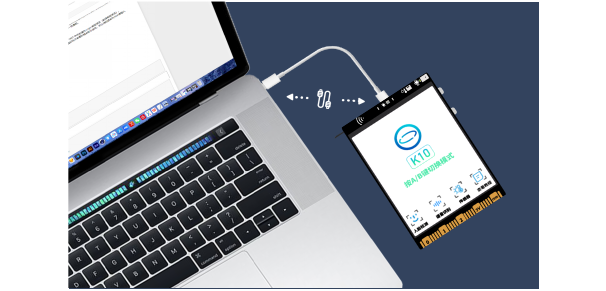
Then, after clicking Connect Device, click COM7-UNIHIKER K10 to connect.

Note: The device name of different UNIHIKER K10 may vary, but all end with K10.
In Windows 10/11, the UNIHIKER K10 is driver-free. However, for Windows 7, manual driver installation is required: https://www.unihiker.com/wiki/K10/faq/#high-frequency-problem
Hands-on Practice
Let's start working on today's course task. We will begin by adding supermarket products and gradually learn how to use the RFID module on the UNIHIKER K10 to recognize and settle the products.
Task 1: Building the Supermarket
In this part, we will add products to the supermarket, create the supermarket homepage, and allow customers to enter the product selection page by pressing a button.
Task 2: Product Recognition
In this part, we will use the RFID module to recognize the corresponding products, and display the quantity of the products in the selection interface.
Task 3: Product Checkout
In this part, we will calculate the total price of the products and perform checkout.
Task 1: Building the Supermarket

Hardware Setup
Make sure to use a USB cable to connect the UNIHIKER K10 to the computer.
Software Preparation
Ensure that Mind+ is open, and the preset code appears in Python graphical mode, successfully loading the UNIHIKER K10. Then, you can start writing the program for the project.

1.Write the Program
STEP 1: Add products and create the supermarket homepage
We have three fruits: pears, apples and bananas in our supermarket. Think about how we can record the prices of the products customers buy in our supermarket.

We need to record the quantity of each product purchased and multiply it by the unit price to calculate the total price. Therefore, we need to use variables to store the quantities of the products, as well as another variable to calculate the total price. Thus, we need to create four variables: "pear", "banana", "apple", and "total price". The initial value for the products should be set to 0. The related program is as follows:

Once the products are added, we need to create the supermarket homepage. We can use the "cache local image" command to add the homepage image, setting the width and height. The related program is as follows:

The display effect is as follows:

STEP2: Enter the Product Selection Interface
After creating the supermarket homepage, how can we set the condition to enter the product selection interface?

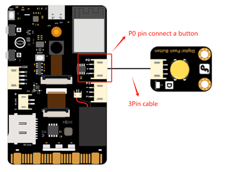
We can connect a button to pin P0 of the UNIHIKER K10. When the button is pressed and the value of pin P0 is read as 1, the system will automatically jump to the product selection interface. To read the value from pin P0, we can use the "read digital P0" command in the pin operation module.
You can connect a button to pin P0 using a two-pin PH2.0-3P silicone cable as shown in the diagram below:
The related program setup is shown in the diagram below:

Note: For more information about "Pin", refer to the "Knowledge Hub".
STEP 3: Add RFID Module
To enable the supermarket to use RFID technology for product checkout, we need to add the RFID module to our supermarket. The RFID module is already available in the user library of Mind+.
First, connect the RFID module to the I2C interface of the UNIHIKER K10. Then, initialize the RFID module using the command "initialize RFID module I2C address 0x7c".
The connection of the RFID module to the UNIHIKER K10 is shown in the diagram below:

The usage of the RFID module is shown in the diagram below

The complete code for creating the supermarket module is as follows:

2.Run the Program
STEP 1: Ensure that the UNIHIKER K10 is connected to Mind+, and that the IP address is displayed in the Menu section.

STEP 2: Click the "Upload" button in the upper right corner.

STEP3: At the beginning, load the supermarket home page, press button P0 to jump to the supermarket shopping interface, as shown in the figure below:

Task 2 Product Recognition
1.Write the Program
STEP 1: Get the UID of the Products
In our unmanned supermarket, each product has its corresponding NFC electronic tag sticker. We need to know the value of the NFC electronic tag in order to identify the product.
Therefore, we need to write a program to retrieve the UID values for the three products. We can use the "read RFID module UID" command in the RFID module to display the UID of each card scanned on the UNIHIKER K10 screen and record them accordingly. The related program is shown in the diagram below:

After uploading the program, bring the three cards close to the RFID module and record the UID values for each product. The result should look like this:

Note: Different NFC electronic tags have different UID values, so you will need to read them yourself
STEP 2: Display the Quantity of Products Purchased
Once we have obtained the UID values for each product's NFC tag, we need to compare them. If the UID of the electronic tag card selected by the customer matches the corresponding UID, the quantity for that product should be incremented by 1, and the corresponding value should be displayed in the quantity column. The related program is shown below:

The complete code for the product recognition module is as follows:

2.Run the Program
STEP 1: Connect the UNIHIKER K10.
STEP 2: Click the "Upload" button in the upper-right corner.
STEP 3: In the product selection interface, place the NFC electronic tag cards for different products on the RFID reader and observe the changes in the quantity of the corresponding products.

Task 3: Product Checkout
In this task, we need to calculate the total price of the products based on the quantities obtained earlier, and allow the customer to press a button to go to the payment page
1.Write the Program
STEP 1: Calculate the Total Price of Products
We use the "Detected card?" command in the RFID module. When a card is detected, we first use the previous program to get the quantities of the products. Then, we need to multiply the quantity of each product by its unit price to calculate the total price, and display it in the corresponding position. The related program is shown below:

STEP 2: Proceed with the Payment
After the customer finishes shopping, they can press a button to go to the QR code payment page. Therefore, we need to connect a button to pin P1 of the UNIHIKER K10. When the button is pressed, the product checkout program will stop, and it will jump to the QR code payment interface.
You can connect a button to pin P1 using a two-pin PH2.0-3P silicone cable as shown in the diagram below:

The related program setup is shown below:

Complete program reference is shown below:

2.Run the Program
Click the "Upload" button. After completing the checkout, press the P1 button to jump to the QR code payment interface. The result is shown below:

Knowledge Hub
1.What is a Digital Input Signal?
A digital signal refers to a signal described by a set of special data, 0 and 1. The value 1 represents a signal presence, while 0 represents no signal. The reason for using 0 and 1 to represent digital signals is that circuits have only two states: on and off. A digital signal of 1 means the circuit is connected (on), while a digital signal of 0 means the circuit is disconnected (off).

A digital input signal refers to the signal collected by a digital sensor, and the collected signal has only two possible values: 0 and 1.
In the program, when a button is pressed, the returned value is 1 - true; when the button is released, the returned value is 0 - false.
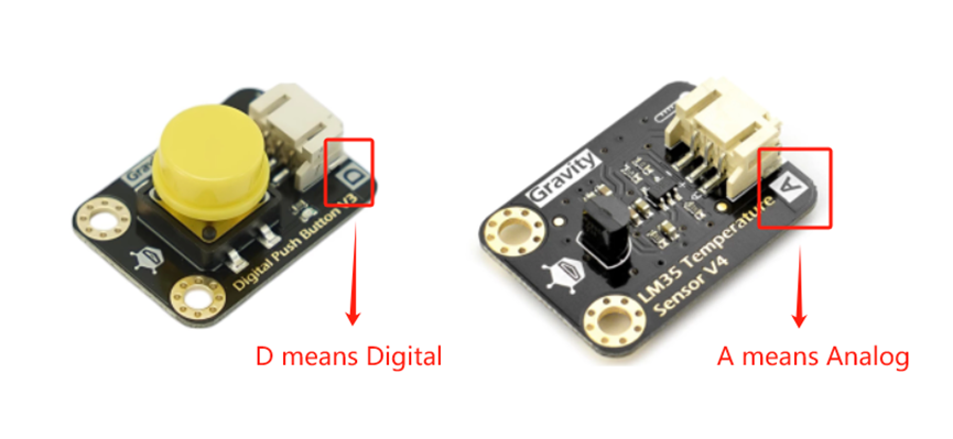
So, how can we tell if a sensor is a digital sensor? The sensor board will have the letters "D" and "A" printed on it. "D" represents "digital," and "A" represents "analog." A sensor marked with "D" is a digital sensor, and a sensor marked with "A" is an analog sensor. Information on analog sensors will be introduced when using analog sensors.
On the UNIHIKER K10, there are two 3-pin pins, P0 and P1. Both of these pins can be used to connect digital sensors, as well as PWM sensors (such as servos) and analog sensors. Information about PWM will be provided when using PWM sensors.

2.Understanding Pins
Pins are the connections from the integrated circuit's internal circuits to the external circuits. In simple terms, pins are the interfaces between the UNIHIKER K10 and the external environment. Through pins, we can read external data and control external devices.
In the UNIHIKER K10, there are two 3-pin interfaces and one 4-pin interface. The two 3-pin interfaces support digital input/output, analog input, and PWM output, allowing flexibility to handle various control needs. The 4-pin interface is an I2C interface, which can be used to connect devices such as gesture recognition sensors and RFID modules, expanding the device's functionality and supporting a variety of application scenarios.
3.Pin Operation Commands
The pin operation commands for the UNIHIKER K10 are as follows:

The UNIHIKER K10 Smart Supermarket project brings advanced computing into the classroom. By building an RFID-enabled retail system, students gain practical experience in hardware programming, sensor integration, and digital signal processing—all through an easy-to-learn graphical interface. Whether you're an educator or maker, this project showcases how accessible IoT can be for the next generation of tech innovators.
[Get UNIHIKER K10 here]
Want to keep learning? Continue your learning journey with our other lessons.
Lesson1: Build a Light-Responsive Virtual Pet Dog
Lesson2: Design a Whack-a-Mole Arcade Game
Lesson3: Build Portable Walkman-Style Music Player (KS3/CSTA/DigComp)
Lesson5: Build IoT Smart Greenhouse Monitoring System
Lesson6: Build a Voice-Controlled Smart Home Assistant
Lesson7: Build a Face Recognition AI Camera for Christmas Projects
Lesson8: Create an AI-Powered Campus Gatekeeper with Facial Recognition
Lesson9: Create an Automatic Cat Feeder with Cat Face Detection


![[Spanish ver.] HuskyLens Cámara Inteligencia Artificial](https://dfimg.dfrobot.com/nobody/makelog/902f49d1d2eb94077e1ba7d8b652cee6_224x164.jpg)


